Solid Sample Reflectance Measurements
In addition to measuring liquids, UV-VIS spectrophotometers are used to measure the transmittance and reflectance of solid samples. Of the two types of reflectance measurements—relative reflectance and absolute reflectance, this issue is mainly focused on relative reflectance measurement.
1. Reflectance Measurement
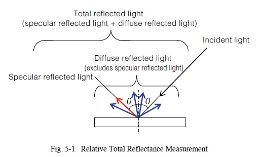
Reflectance is measured by shining light on a sample and measuring the light reflected from the sample. Reflected light consists of specular reflected light and diffuse reflected light, which when combined together is referred to as total reflected light (specular reflected light plus diffuse reflected light). Fig. 1 shows a diagram of these types of light. The light shone onto the sample is called the incident light and the angle formed between the incident light and sample is called the angle of incidence. In Fig. 1, the incident angle is represented with the symbol θ.
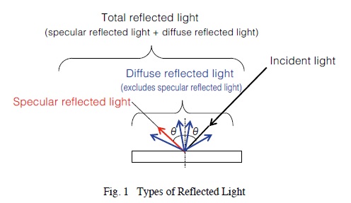
Specular reflected light is the light reflected from shiny mirror-like surfaces at the same angle as the incident angle. Diffuse reflected light is the diffuse light reflected in all directions from rough surfaces, such as paper and powder surfaces. Total reflected light is the total combination of specular and diffuse reflected light. Total reflected light is often measured when measuring samples that have both rough and shiny characteristics, such as plastic and painted samples. The methods used to measure specular, diffuse, and total reflected light are referred to as specular, diffuse, and total reflected light measurement methods, respectively.
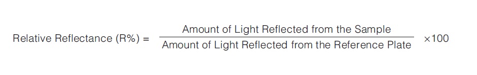
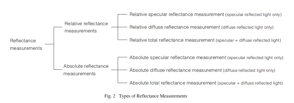
Reflectance measurements measure either the relative or absolute reflected light, with measurement values expressed in terms of reflectance. Relative reflectance measurements calculate the proportional amount of reflected light measured from a sample surface, relative to the amount of reflected light measured from a reference plate, such as barium sulfate or a mirror. The relative reflectance is calculated based on assuming the reference plate has a reflectance of 100 %. Therefore, it is very important to manage reference plates properly because different reflectance values can be obtained if reference plates are substituted or if they become contaminated or change characteristics.
In contrast, absolute reflectance measurements calculate the proportional amount of reflected light relative to the amount of light measured directly from a light source, not using a reference plate such as barium sulfate or a mirror. Reflectance measurement values are based on assuming a 100 % reflectance for air. Absolute reflectance measurements allow determining the true reflectance of samples, which is referred to as absolute reflectance.

Reflectance measurements can be categorized as shown in Fig. 2.
2. Relative Specular Reflectance Measurement
Relative specular reflectance measurements involve shining light on the sample, and measuring the specular light reflected at the same angle as the incident light, as shown in Fig. 3-1. Relative specular reflectance measurements are especially useful for measuring thin films on a mirror or metal surface.
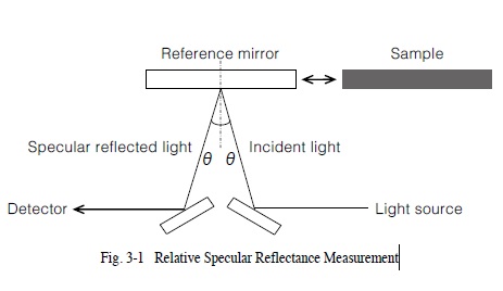
Fig. 3-2 shows a specular reflectance measurement attachment used to measure relative specular reflectance. The incident angle of this attachment is 5 degrees (the angle represented by θ in Fig. 3-1). The aluminum-coated mirror is typically used as the reference plate for measurements using the specular reflectance measurement attachment. Samples are placed with the measurement surface facing downward.
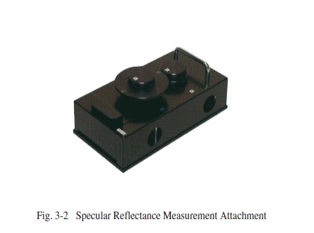
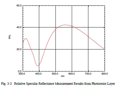
Fig. 3-3 shows results from measuring a photoresist layer on a wafer using a specular reflectance measurement attachment. This provides the relative reflectance of the sample relative to the aluminum-coated mirror that was used as the reference. However, this specular reflectance measurement attachment cannot be used to measure the diffuse light reflected from samples with a rough surface.
3. Relative Diffuse Reflectance Measurement
Relative diffuse reflectance is measured by using an integrating sphere to measure the diffuse reflected light with specular reflected light excluded, as shown in Fig. 4-1. This is used to measure samples with a rough surface, such as paper.
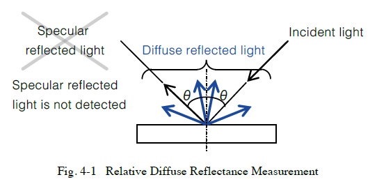
Fig. 4-2 shows an integrating sphere attachment used to measure relative diffuse reflectance. When using an integrating sphere, a material such as barium sulfate or specialized fluorine-based polymer (see Note 1) is used as the reference plate (sometimes referred to as a white reference plate).
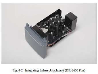
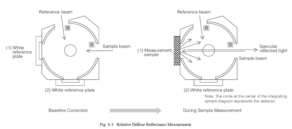
Fig. 4-3 shows a diagram of the measurement. The measurement procedure is as follows.
1. Attach a barium sulfate or other white reference plate at position (1) in the integrating sphere shown in Fig. 4-3. Perform baseline correction. The sample beam shines on the white reference plate.
2. Remove the white reference plate from position (1) in Fig. 4-3 and attach the measurement sample in its place. Measure the sample to obtain the diffuse reflectance. Specular reflected light is reflected out of the integrating sphere via the sample beam inlet port and, therefore, is not detected (see Note 2).
Diffuse reflected light is measured using an integrating sphere according to the procedure indicated above.
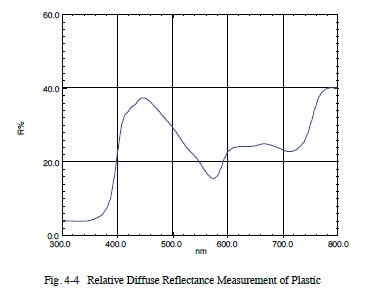
Fig. 4-4 shows the results from measuring the relative diffuse reflectance from a plastic surface using an integrating sphere with barium sulfate as the white reference plate.
Note 1: Due to a small amount of water contained in barium sulfate, using it as the white reference plate for reflectance spectrum measurements in the infrared region may result in effects from water absorption near 1450 nm, 1950 nm, and 2500 nm. In contrast, the special fluoropolymer does not contain any water, so spectra are not affected by water.
Note 2: The purpose of the reference beam indicated in Fig. 4-3 is for correcting light source fluctuations in real time. For more information regarding the role of the reference beam, refer to UV TALK LETTER Vol. 9.
4. Relative Total Reflectance Measurement
Determine relative total reflectance by measuring all the reflected light, including both specular and diffuse reflected light, as shown in Fig. 5-1. This is effective for samples with either rough or shiny surfaces
Relative total reflectance is measured using an integrating sphere attachment. Relative total reflectance is measured by shining light on the sample at an incident angle of about 10 degrees or less (8 degrees for Shimadzu integrating spheres) and using an integrating sphere to measure not only the diffuse reflected light, but also the specular reflected light.
Typically, a white plate with a rough surface, such as barium sulfate, is used as the reference plate. However, unlike relative diffuse reflectance measurements that do not include specular reflected light, aluminum-coated mirrors are also often used as the reference plate (see also Precautions for the Reference Plate Used for Total Reflectance Measurements).
Fig. 5-2 shows a diagram of the measurement. The measurement procedure is as follows.
- Reverse the roles of sample and reference beams in measurement parameter settings. In Shimadzu software, this means setting the S/R switching function to reverse.
- Attach a white reference plate at position (2) of the integrating sphere shown in Fig. 5-2. Perform baseline correction. The sample beam shines on the white reference plate.
- Remove the white reference plate from position (2) in Fig. 5-2 and attach the measurement sample in its place. For Shimadzu integrating spheres, the beam shines on the sample at an incident angle of 8 degrees.
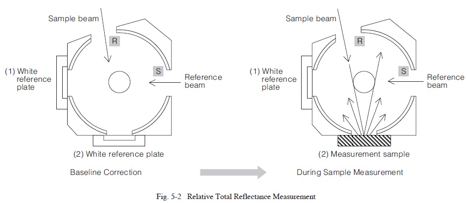
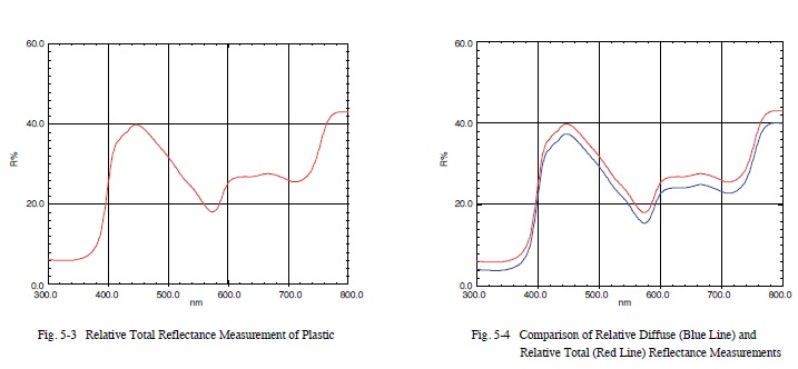
Fig. 5-3 shows the results from using a barium sulfate reference plate to measure the relative total reflectance of the plastic measured in 3. Relative Diffuse Reflectance Measurement. Fig. 5-4 shows a comparison of the relative diffuse reflectance spectrum and relative total reflectance spectrum. Because the relative total reflectance includes the specular reflectance components, the reflectance level is higher than the relative diffuse reflectance.
Precautions for the Reference Plate Used for Total Reflectance Measurements
To match the light scattering status in the integrating sphere during sample measurements and baseline correction as closely as possible, use a reference plate with a shiny surface, such as an aluminum-coated mirror, to measure samples with predominantly specular reflectance. To measure samples with predominantly diffuse reflectance, use a reference plate with a rough surface, such as barium sulfate.
For example, if an aluminum-coated mirror is used as the reference plate for measuring the total reflectance of paper, the reflected light first hits in a different location inside the integrating sphere during sample measurement compared to during baseline correction. The light scattering status during sample measurement remains different from the status during baseline correction throughout the measurement, and this difference is added to measurement values. (These effects are due to differences in the status of scattered light and the fact that the internal surfaces of the integrating sphere are not completely uniform.) Therefore, measurement results include a certain error factor. When using systems that switch between different detectors, this can cause a discontinuity in measurement data at the wavelength where the detectors are switched. In contrast, if the paper is measured using barium sulfate as the reference plate, the reflected light initially hits about the same position inside the integrating sphere during both sample measurement and baseline correction. Consequently, correct relative reflectance values are obtained.
For the same reason, a mirror surface, such as an aluminumcoated mirror, must be used as the reference plate for measurring the relative total reflectance of films and coatings on a predominantly mirror-like (shiny) surface, such as metal substrates.
That is the reason that reference plates with shiny surfaces are used to measure shiny samples and reference plates with diffuse surfaces are used to measure diffuse samples.
5. Summary
This issue describes the measurement principle, measuring method, and precautions mainly for relative reflectance measurements. The reflectance measurement method used differs depending on the sample surface status and objectives.
Hopefully this explanation will provide a helpful reference.