Learning About Electronic Balances
As of 2008, Shimadzu has been manufacturing balances for 90 years. During that period, the most revolutionary event was electrification and the advent of the electronic balance. Due to their easy operation and fast measurement, their use has spread very quickly.
However, there are also hidden pitfalls to their ease-of-operation and convenience that could result in committing major mistakes.
Therefore, this page discusses the key points for ensuring electronic balances are used correctly and more accurate and reliable measurements are obtained. The following describes the types of error, how each type occurs, and measures to minimize error. In addition, we will also give some recommendations for daily inspections (including adjusting sensitivity).
(1) How Electronic Balances Work
(2) Types of Error
(3) Causes and Corrective Measures for Error
(4) Inspections
How Electronic Balances Work
The quickest way to understand the principle of how electronic balances work, is to first understand how they are constructed. There are two basic types of electronic balance designs.
1. Electromagnetic balancing type
2. Electrical resistance wire type (load cell type)
These are based on completely different principles, but what they both have in common is that neither directly measures mass. They measure the force that acts downward on the pan. This force is converted to an electrical signal and displayed on a digital display.
As a means of measuring force, the electromagnetic balance method utilizes the electromagnetic force generated from a magnet and coil, whereas the electrical resistance wire method utilizes the change in resistance value of a strain gauge attached to a piece of metal that bends in response to a force.
Note: See also the article on Electromagnetic Versus Load Cell Type Balances
So why do electronic balances display mass values when that is not what they measure? It is because the reference standards for mass are weights, which are placed on a pan to inform the electronic balance that a given force is equivalent to a given number of grams, which is used for conversion. Consequently, electronic balances that do not perform this conversion accurately cannot display accurate mass values.
Types of Error
1. Sensitivity Error
This indicates a difference between the value measured by the balance and the correct value. Normally, this is expressed in terms of the deviation at measurement points near the balance capacity (maximum mass measurable). As an extreme example for a balance with a 200 gram capacity, if a 200 g weight is placed on the pan but the balance displays a value of 160 g, the sensitivity error at 200 g is -40 g. This indicates that the deviation is distributed proportionally as error over the entire measurement range. For example, a measurement at 100 g is half the weight of 200 g, so it would include half the error of 200 g, or -20 g.
Sensitivity error occurs based on how accurately calculations are performed when force is converted to mass, as described above in How Electronic Balances Work. The method used to convert force to mass is always described in instruction manuals and is referred to as sensitivity adjustment, calibration, or span adjustment. Placing the balance in different locations can results in variations in gravitational acceleration or variations in room temperature that can affect conversion. Sensitivity error can increase or decrease depending on how users adjust sensitivity.
2. Linearity Error
If the error included in balance measurement values was only the sensitivity error described above, then error would be proportional to the load value at any given measurement point. However, in reality that is not the case. That is because there are other types of error besides sensitivity error. One such error is linearity error, described in this section. The relationship between sensitivity error and linearity error is explained in Figure 1. (It shows an example of an especially large error for illustrative purposes.)
Assuming the measurement value for a 200 g weight on a 200 g balance is indicated as 160 g (sensitivity error of -40 g), then measurements of 100 g should include a proportional sensitivity error component of -20 g, resulting in a measurement value of 80 g. In other words, measurements should fall along a straight line connecting the measurement at 200 g and the origin (the sensitivity line of the balance). The area between this balance sensitivity line and an ideal line with zero error represents the sensitivity error component. However, in reality, measurements sometimes do not fall along the balance sensitivity line. For example, if the measurement value for 100 g was 50 g, then it includes an additional error of -30 in addition to the 80 g indicated by the balance sensitivity line. This additional error component is referred to as the linearity error.
Linearity error occurs due to the state of the balance itself or its original performance level. (This value is indicated in the instruction manual specifications included with each balance.) Therefore, this error level cannot be reduced by the user. Nevertheless, the sensitivity error component can be minimized by properly adjusting the sensitivity.
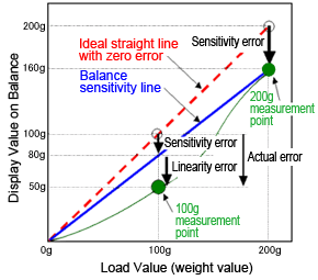
Balance Error - Sensitivity and Linearity
It is important to determine the composition of error in balance measurement values. In other words, it is important to determine what component of error is due to sensitivity error and what component is due to linearity error. To use the balance properly, rather than assuming the balance has malfunctioned just because the error is large, it is extremely important to always consider whether the error is due to sensitivity error or not.
3. Repeatability
Repeatability refers to the degree to which the same measurement value is obtained when repeatedly measuring the same thing and is an indication of precision level. It expresses the variability of measurement values in terms of standard deviation or band width.
Repeatability depends on the status of the balance itself and original performance level, but it also depends on how it is used (such as the containers used for measurements) and the environment (such as effects from air flow or static electricity).
4. Eccentric Error
This error occurs due to where the item is placed on the pan. In the case of round pans, this is expressed as the difference in measurement values obtained when an item is placed half a radius away from the center, in 45-degree directions (front left, front right, rear right, and rear left), compared to the measurement at the center. Eccentric error depends on the status of the balance itself and its original performance, but can be significantly reduced by being careful to place loads in the pan center.
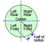
Eccentric Error of Balances
Causes and Corrective Measures for Error
By understanding how error occurs and the factors that cause it, methods of minimizing error become apparent. The following describes some of the main factors that cause error, along with measures to minimize them.
1. Gravitational Acceleration
The biggest factor causing sensitivity error is gravitational acceleration.
Consider the following example. If a balance with sensitivity adjusted perfectly in Tokyo is transported carefully to Kagoshima (about 1000 kilometers southwest of Tokyo) without causing any damage, the measurement value for a 1 kg weight would change as indicated below.
Tokyo: 1000.00 g
Kagoshima: 999.70 g
This phenomenon is due to the difference in gravitational acceleration resulting from the difference in latitude. In other words, a sensitivity error occurs, where the balance measurement values become smaller as you move south and larger as you move north.
Gravitational acceleration is not only affected by latitude, but also by altitude as well.
The important point here is not about how much of a sensitivity error occurs for a given movement of the balance, or by a given change in floors of a building, rather the point is that sensitivity should be readjusted whenever the balance is moved, even for short distances.
2. Temperature
The second biggest factor causing sensitivity error is temperature. Temperature variations in the balance itself can cause sensitivity error.
Electronic balance specifications always specify a temperature coefficient for sensitivity. This value indicates how much balance sensitivity error occurs for each degree change in temperature. The following example of an analytical balance shows how much the display value can vary.
Temperature Coefficient for Sensitivity: 2 ppm/°C
Before Temperature Change: 200.0000 g
After 5 °C Change: 200.0020 g
One of the factors that causes balance temperature to change is room temperature. If your laboratory temperature stabilizes quickly to an appropriate temperature each morning, you may think there is no problem with temperature, but the balance itself does not change temperature as quickly as the room temperature.
It takes a long time for it to gradually adjust to temperature changes.
In some cases, if the balance sensitivity is adjusted after the air conditioner is switched on and the room temperature has stabilized in the morning, it may be possible to adjust the sensitivity at that time, but it will immediately start changing again. Eliminating room temperature variations is best, but as a practical matter we recommend performing the most important measurements (those that require the most precision) in the afternoon (after the balance has thoroughly adjusted to the room temperature). Also, always remember to adjust sensitivity immediately before measurements.
Other factors, besides room temperature, that change the balance temperature include direct sunlight and heat generated by electronic parts within the balance. To avoid these factors, keep the balance away from direct sunlight and, if possible, leave the balance power ON 24 hours a day.
3. Containers
Have you had the following experience? Using flasks or other such containers can cause a drifting phenomenon, where the indicated balance value gradually changes in one direction. This is due to the air contained in the container. For example, if the container has a lower temperature than the weighing chamber, the air in the container is heated by the interior of the weighing chamber, causing the air to expand and overflow from the container. Therefore, the indicated value on the balance gradually creeps lower.
Given a container volume of 100 cm3, a change in container temperature of 2 °C is equivalent to 0.82 mg. These conditions will cause measurement repeatability to increase (become worse). To avoid this situation, have the container adjust to the balance temperature as much as possible, such as by leaving the container next to the balance and not touching the container with bare hands.
4. Air Flow
It is easy to imagine how the beam of a mechanical weighing balance could fluctuate when exposed to external air flow. The same thing applies to electronic balances as well. The presence of air flow can cause worse stability and repeatability or other consequences.
1) Air Flows From External Sources
There are many factors in our immediate surroundings that can cause air flow, such as air conditioners and the movement of people, but one factor that is often overlooked is the door to the room. If the door is a swinging type, think of it as fan that not only generates it own wind, but also changes the room air pressure, which disturbs the stability of the air inside the balance as well. These effects can be significantly prevented by taking measures with respect to the facility to prevent exposing the balance to air flow and having all personnel, including those not involved in using the balance, to cooperate together in being careful. Also, if possible, use a sliding type door.
2) Air Flows Generated Within the Weighing Chamber
If the air inside the weighing chamber convects, the pan and item being measured will be exposed to air flow, which will cause instability.
Convection can be caused by factors such as the rise or fall of air due to temperature differences between items being measured and the weighing chamber or the disturbance of air from moving items being measured in and out of the weighing chamber. To minimize convection, it is necessary to keep in mind to let items being measured thoroughly adjust to the balance temperature, to avoid inserting hands into the weighing chamber, to place or remove items being measured in as short a time as possible, and to avoid opening the weighing chamber door more than necessary. In addition, to minimize temperature differences between inside and outside the weighing chamber, we recommend leaving the weighing chamber door open a few millimeters when the balance is not in use. However, no matter how careful you are, it is difficult to completely suppress convection. Therefore, to minimize its effect, do not let items being measured protrude from the pan. Success comes from paying attention to details, such as folding the edges of weighing paper.
5. Static Electricity
Static electricity, which appears when the air starts becoming dry, can electrically charge powders, plastic or glass containers to cause the balance display value to be unstable and cause repeatability to become worse. If a problem occurs only when weighing an actual sample, but not when weighing weights, then the cause is likely static electricity.
Static electricity can be discharged to the air and eliminated by humidifying the room, but using an ionizer is also effective. Shimadzu offers STABLO-AP ionizers.
Electronic balance error was discussed above. Hopefully, this will be helpful to those that read it. In addition to the causes mentioned above, there are a variety of factors that can cause errors, such as vibration and the density of the items being measured. Those will be discussed in a future article, as opportunity allows. Next, we will give a brief introduction to daily inspection of balances.
Daily Inspection of Balances
Inspect the following every day or before use, as described below, to confirm with minimal operations that the analytical balance will function properly. To inspect the weighing capacity, place a weight with a known mass on the pan to confirm that the displayed value is within the criteria values (user-specified values). It is also necessary to decide what procedure should be followed if the value exceeds the criteria values, such as whether to readjust the balance until the value is within the criteria values or send the balance out for repairs. In recent years, routine inspections have been increasingly performed at two or three inspection points, typically including one point near the weight where the balance is normally used and one near the weighing capacity. As indicated in Table 1, routine inspections should inspect both performance and the general status of the electronic balance, such as checking for contamination on the pan or in the weighing chamber and checking that the digital display functions properly. Table 2 shows an example of a routine inspection results record.
Table 1: Content of Routine Inspections
|
Inspection Item
|
Inspection Method |
Control Criteria
|
Corrective Actions
|
|---|---|---|---|
| (1) Installation Site | Check the support base (for stability). Use a level gauge to confirm it is level. |
Confirm the desk or other support base is stable and level. | Provide proper installation site conditions. Level the balance. |
|
(2) Pan and Weighing Chamber
|
Check for contamination from sample debris. | No sample debris No contamination |
Wipe with alcohol or other solvent. Clean with a brush. |
|
(3) Functionality
|
Connect to power sufficiently and inspect the digital status. | Display value remains stable. | If the display is unstable even without external disturbances, then have it repaired. |
| (4) Performance | After calibration, select a weight equivalent to the weighing capacity of the balance. | Value is within operating tolerance. | If within tolerance, the routine inspection is finished and normal operation may start. |
Table 2: Routine Inspection Results Record (Example)
|
Inspection Date
|
Condition of Electronic Balance |
Performance, Weight No. Used, and Measurement Value
|
Result
|
Inspected By
|
|---|---|---|---|---|
|
Sep. 14, 2017
|
No problems
|
200.0005 g using weight A-01
|
OK
|
David Shimadzu
|
|
|
|
|
(Fill out before starting operations each day. In particular, be sure to indicate the number of the weight used.)
Periodic Inspections
Periodic inspections generally include the routine inspection items (1) to (4) above, plus three additional performance inspection items: (5) repeatability, (6) eccentric (corner load) error, and (7) instrumental error (linearity). Hysteresis and drift are also inspected as necessary. The frequency of periodic inspections is not specified by law. That means users need to decide inspection frequency based on their application and required specifications. In recent years, inspections have been typically performed once every one or two years. The following explains specifically how performance is inspected during periodic inspections.
(5) Repeatability (For the dual range, inspect both small and large ranges.)
Inspect repeatability according to the following procedure.
- For models with internal calibration weights, calibrate the balance using the internal weights.
- Record the zero point and loaded weight value when loading and unloading a single weight (up to two weights in unavoidable circumstances) that is about one half of the weighing capacity or heavier. Do that five times. Alternatively, instead of recording the zero point measurement value, the display can be reset to zero each time before loading the weight and recording the weight value.
- Determine the range (maximum minus minimum value) for the zero points and loaded weight values (or only the loaded weight value if the zero points were not measured in the previous step). The balance passes the inspection if the range value is within the specified tolerance.
(6) Eccentric (Corner Load) Error (For the dual range, inspect only the large range.)
Inspect eccentric (corner load) error according to the following procedure.
- Place a single weight that weighs about 1/3 to 1/2 of the balance weighing capacity successively in the positions shown in Figure 1 (center, right-front, right-rear, left-rear, left-front, and center) and record the measurement value at each position. (For the center position, place the weight in the center of the pan. For the other positions, place them in the center of corresponding quadrants of the pan. For a round pan, for example, offset the weight one half the pan radius from the center.)
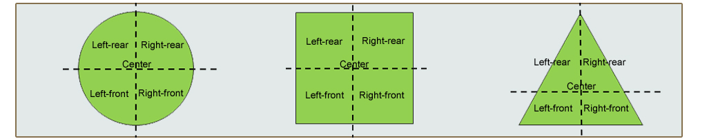
Figure 1: Weight Positions for Eccentric (Corner Load) Error Inspection
- Calculate the difference between the value measured at each non-center position and the average value of the two center values (referred to as the eccentric error). The balance passes the inspection if the difference is within the specified tolerance. Instead of the average of the two values measured at the center, the eccentric error may also be determined as the difference with respect to the initial center value.
(7) Instrumental Error (Linearity) (For the dual range, inspect both small and large ranges.)
Inspect instrumental error (linearity) according to the following procedure.
- Specify at least four observation points, including near the balance weighing capacity. Specify the observation points based on the following criteria
A) At or near equal intervals throughout the weighing capacity
B) At points where the inspection tolerance changes
C) In load regions identified as important by the person requesting the inspection
- Place the weight for each specified observation point in the sequence indicated below and record the measurement values. Zero point → First observation point (smallest weight) → Second observation point → Third observation point → Largest observation point (near weighing capacity) → Zero point Alternatively, instead of recording the zero point measurement value, the display can be reset to zero each time before loading the weight and recording the weight value.
- Subtract the average of the first and last zero point values from the measurement value at each observation point. (This step is not necessary if the zero points were not measured in the previous step.)
- Calculate the difference between each value determined in the previous step and the certified value measured by placing a weight on the pan. (That difference is referred to as the instrumental error.) The balance passes the inspection if all the instrumental error values are within the inspection tolerance. We hope this explanation of balance inspection provides a useful reference for your routine analysis operations.
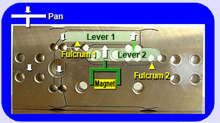
An Interesting Mechanism - The Unibloc
In the introduction of this discussion "electromagnetic balance method" was mentioned as one type of electronic balance. The electromagnetic balance method is widely used in high precision electronic balances. Typically, the mechanical portion of balances that receive loads is the heart of the system, which is made from a complicated combination of many parts. However, Shimadzu has succeeded in integrating that mechanical assembly into a single aluminum part, machined from a single block of aluminum. Therefore, we named this unique part that packs so much sophisticated technology into a single part "Unibloc." A brief overview is provided below.
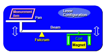
To put it simply, the structure of electromagnetic type balances is based on a lever. The pan with the item being measured is attached to one end of the lever and a coil that generates an electromagnetic force is attached to the other end. See the diagram below. However, the actual structure is much more complicated.
The Unibloc comprises the key parts of this lever mechanism, carved from a single block of aluminum. Furthermore, two stages of levers are carved from the block.