Particle Size Distribution Calculation Method
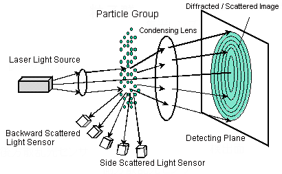
Fig. 1 Basic Optical System of a Laser Diffraction Particle Size Analyzer
As shown in Fig. 1, the diffracted/scattered light intensity distribution pattern is generated spatially when a measurement target particle group is irradiated with a laser beam. The light intensity distribution pattern of the forward scattered light is condensed by the lens, and a ring-shaped diffracted/scattered image is formed on the detecting plane located at the focal distance. This is detected by a ring sensor comprising sensing elements placed concentrically. Side scattered light and backward scattered light are detected by side scattered light sensors and backward scattered light sensors, respectively. In this way, various sensing elements are used to detect the light intensity distribution pattern to obtain light intensity distribution data.
The light intensity distribution data changes according to the size of the particle. Because actual samples contain a mixture of different size particles, the light intensity distribution data generated from a particle group is the result of overlaid diffracted/scattered light from each respective particle.
This phenomenon can be expressed as follows using expressions (vector and matrix):
where,
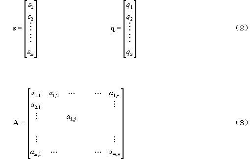
is the light intensity distribution vector. Its element si (i = 1,2, ......m) is the amount of incident light detected by each sensing element of the ring sensor and the side/backward scattered light sensors.
q is the particle size distribution (frequency distribution %) vector.
The measurement target particle size range (max. particle size: x1, min. particle size: xn+1) is divided intonseparate intervals, and each of these particle size intervals is taken to be [xi, xi+1] (j = 1,2,.... n). The element of q qj(j= 1,2,....n) is the particle amount corresponding to the particle size interval [xi, xi+1]. Normally, the volume standard is used.
Namely, normalization is performed so that the total becomes 100%.
A is the coefficient matrix for converting particle size (vector) q to light intensity distribution (vector) s.
The physical meaning of the element of A ai,j(i = 1,2, ....m, j = 1,2, ....n) is the amount of light incident on the ith element of the light diffracted/scattered by the particle group of unit particle amount belonging to particle size interval [xi, xi+1]. To put it another way, this coefficient matrix A expresses the diffraction/scattering phenomenon itself.
The numerical value of ai,j can be calculated theoretically beforehand. To calculate this, the Fraunhofer diffraction theory is used when the particle size is sufficiently larger (ten times or more) than the wavelength of the laser beam used as the light source. However, the Mie scattering theory must be used in regions smaller than that. The Fraunhofer diffraction theory can be considered to be a superior approximation of the Mie scattering theory, which is valid when the particle size is sufficiently larger than the wavelength in the forward small scattering angle region.
To calculate the elements of coefficient matrix A using the Mie scattering theory, the absolute refractive index (complex number) of the particles and the dispersion medium (liquid medium) must be set. The least square's solution of particle size distribution (vector) q can be obtained using the following expression based on expression (1):
where, AT expresses the transposed matrix, and () -1 expresses the inverse matrix.
Each element of light intensity distribution (matrix) s on the right side of expression (5) is a numerical value detected by the ring sensor and the side/backward scattered light sensors. Coefficient matrix A can be calculated in advance using the Fraunhofer diffraction theory and Mie scattering theory. Consequently, particle size distribution (vector) q will be obtained if calculation of expression (5) is executed using these known data.
This expression (5) is the basic method in the laser diffraction/scattering method for calculating the particle size distribution from light intensity distribution data. However, note, that since a fairly large error occurs merely by executing this expression as it is, the calculation that is actually executed on the computer is complex with a variety of conditions factored in. For example, additional restrictive conditions, such that the particle amount must not become a minus numerical value or the particle size distribution must to a certain extent be continuous, are included in the calculation.
Moreover, when measuring or re-calculating the particle size distribution, the fact that refractive index is selected means that coefficient matrix A, that is calculated using that refractive index, is actually selected. In wet measurement using the SALD series, the refractive index of the medium (liquid medium) is fixed to the refractive index of water, and only the refractive index of the particles is selected. Likewise, with dry measurement, the refractive index of the medium is fixed to the refractive index of air, and only the refractive index of the particles is selected.
As described above, on a laser diffraction particle size analyzer, that uses the laser diffraction/scattering method as its principle of measurement, it is the particle amounts of each preset particle size interval that are initially measured (calculated). That is, the particle size is not measured (calculated); it is the particle size distribution that is measured (calculated).
Median diameter, arbitrary % particle size and average particle size are indirectly calculated from the particle size distribution that is obtained.